Designing for Safety Systems: Fail-safes & Redundancy

Sometimes engineering requires the consideration of the specific working environments such as certain industry, transport, military and aerospace due to dangerous chemicals, harsh dirty geography or more prominently where human life could potentially hang in the balance.
The hazards of the specific environment call for different considerations when designing systems. It is very important to note that when we talk about redundancy implementation it does serve a purpose, as appose to just adding it superfluously.
Redundancy is usually when two of the same component in the system work in parallel with each other, this protects against total system failure or domino effect failures because of a single failure mode in one of the components upstream. A server RAID system is a good example of this.
It is important to highlight failure modes within the system in order to identify the need and method for safe failure, or decreasing the likelihood of failure through redundancy.
An excellent example that can be used is a simple potentiometer based sensor such as the ones used in vehicle accelerator pedals.

 
These sensors are an important part of the engine management system and so have redundancy built into them in the form of a double resistive wiper. These sensors are designed to take a beating from powerful human leg muscles and work for at least the lifetime of the vehicle so they are also ruggedized by a thick plastic casing. 
The main point of this post will be about the trade-offs that occur when implementing these systems and when they should be used.
Despite it being important to vehicle safety the pedal sensor still uses contacts rather than solid state components which raises an important point about the reality of engineering and how budget must still be considered.
Unfortunately there is a trade-off so it is very important to get the mix right.
Let’s consider a normal non-redundant potentiometer circuit.


A simple power supply going into the potentiometer and giving a percentage output of the input voltage.
See my circuit help index page for help with the concepts behind these circuits.
Now let’s consider the implementation of redundancy as in the pedal sensor mentioned earlier.

In the circuit diagram above we start to see the trade-offs in complexity VS system safety, this circuit buffers the input, then uses an adder to give an average of the two sensors that should give the same voltage output. If a potentiometer fails, then the voltage will most likely be floating around at some unknow voltage state.
What if we could control the failure mode of the wiper which is the most likely point of failure, as it is a mechanical system and will degrade over time as it grazes against the resistive element?

I have added pull down resistors to the wipers of the potentiometers so know we can be sure that the wipers will fall to ground if they fail. Now the average output will always fall to half of the sensor output. So now rather than giving an unpredictable output, it is possible to design any subsequent circuitry with these failure modes in mind. It is all about predictability and control when designing these systems but as you can see it is getting progressively more complex...


So it’s all well and good if your system fails safe, but what if your design is good enough that it is not immediately detectable to the user, what if you need failure mode sensing?


Cowboy CNC Machines & Real World Automation?

So as a side project, during the procurement lead times of my main project, I thought I would have a look into the CNC welder that has apparently been playing up at my work.

Keep in mind, I am the only electronic engineer employed at the company in a primarily mechanically based business. As a result, I have dubbed myself the principle, chief, senior electronic engineer of the company, how do you like my LinkedIn profile now!


The designer of the CNC machine built it in his garage and is interesting for three reasons.
  • It is quite impressively complex for something built by one mysterious man.
  • How well does it fair from an industrial automation best-practice point of view?
  • How much work does it take to build one?
Anyway the designer went AWOL a while back, so it is up to me to figure it out from scratch... YES, time to get my hands dirty!
https://media.giphy.com/media/11KzOet1ElBDz2/giphy.gif 


Noodle break: My face as I open the control cabinet for the first time.
 

This is my first time getting stuck into something like this, but I think I can say with confidence that it is perhaps not what you imagine when you say industrial automation, it’s a bit of a jury-rig situation but I think it gives it personality.


I love the computer terminal, oh XP how quaint. 

So it looks like for the most part it will set you back an old desktop computer with a custom PCI module, I was able to download the software for free on my laptop so at least you don’t have to pay for that.


The control cabinet is the interesting part and where wiring conventions best practices or even just color coding can make life a lot easier when trying to debug glitches (as you can see).

The PCI module will connect to the micro-controller in the control cabinet and has various low level Boolean controls that are easily flagged from the computer terminal, quite intuitive actually. Everything is 12v, hooray, at least that’s something I don’t have to worry about.


I expect for more complicated and rugged systems you would use a PLC but for what we are working with a micro-controller is more than adequate. The main problem with the machine is with the relays breaking, solid state components are a good modern alternative, such as opto-decouplers.


Autonomous Robots

Haha... I have finally finished my university dissertation project.

I designed and built a fully working general purpose autonomous system, with an acoustic tracking system to demonstrate its independent nature.

Of course it is a bit cliched to build a robot for your university project, hence the guise of 'autonomous system' which is actually a more industrially used name.

It does still have some academic and industrial merit but I just wanted an excuse to build one as that is my dream engineering job ^^ .


Here is my demonstration video, I am quite proud of what I achieved with a old windows phone and movie maker despite the low resolution.

I am using a National Instruments myRIO if anyone is interested, the project cost me under £100 but I won the myRIO (thanks NI) so I don't know what the total is. Nothing you cannot do with a Raspberry Pi or and Arduino though.

Anyway... I hope you found it interesting.

Wind-up USB Phone Charger

Recently I found myself with some spare time so I have been poking around my room trying to find a quick project that could easily be used everyday. I discovered my wind-up torch which gave me the inspiration for an array of dynamo-powered devices, but then I thought, what about a dumb-USB charger for my phone?

I looked up the USB standards online and I found that they all use 5V supplies with a minimum of 500mA current. Perfect, I can find myself an old motor and design/build a voltage regulator with a USB output.

You will need: Any permanent magnet motor, a bridge rectifier, one 10 kilo-ohm resistor, any 5.6V rated zener diode, a BC108B transistor and a female USB jack.


Above is the circuit diagram for my design, I tried to make it as simple as possible.

The circuit handles any voltage input type, which primarily depends on the motor (remember to use a permanent magnet motor else this will not work). Any negative voltage is removed by the bridge rectifier and the zener diode keeps a constant voltage of 5.6V across it. The resistor dissipates the rest of the voltage while simultaneously regulating the maximum current that can flow through the transistor from C to E (500mA max). We always assume that the voltage drop across B and E is 0.7V so the output voltage is just below 5V, perfect for charging any USB device.

To the left is a diagram for a female USB jack facing outwards, pins 2 and 3 are redundant in dumb charging operations and can be ignored. Vcc can be connected to our 'USB +5V' output and ground can be connected to our 'USB Gnd' output. Connections to the motor wires are arbitrary.

Infrasound, Pitch-shifters and Pigeons


I remember being told a while back about the exceptional hearing range of pigeons and it wasn't until an especially random daydream that I decided to investigate further. I was listening to some electronic music at the time, which subsequently made me wonder about what a pigeon may keep on its MP3 player?

My line of thought does have some academic merit before you judge, so bear with...

Having a personal interest in the signal synthesis involved in making electronic music, made me think about the LFOs or Low Frequency Oscillators artists' use in their instruments to modulate their musical tones. These frequencies are deliberately in the infrasonic range of human hearing so our ears cannot pick them up i.e. 0 - 20 Hz, however what if it is not heard by a human but rather another animal such as a pigeon?

Based on an article by M.Kreithen and D.Quine (1979) pigeons can hear as low as 0.05 Hz in isolated environments allowing them to easily hear the LFO tones, and with their high pitch-sensitivity would make unwanted tones easily perceivable, leaving me to conclude the common bird would probably not be a fan.

Pigeon with headphones
Further reading shows that this increased acoustic range is to allow for the detection of weather systems and geological activity from a long range, as the lower frequencies of the landscape's movements attenuate over a larger distance. This made me think that having this physiology could be quite handy, even if implemented artificially.

The primary focus of interest here is how do I pitch shift my own hearing?

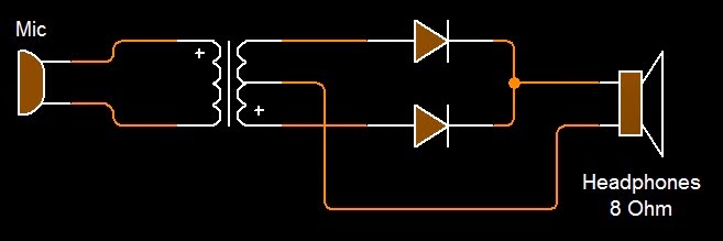
Well I'm sure with a cheap mic and a pair of headphones it should be possible, electronically this can be done by using a simple full wave rectifier circuit which will increase the input signal frequency by two.

Passive Pitch Shifter
This overly-simplified circuit shows the basic concept and could be implemented totally passively through the use of a sensitive mic and germanium diodes that have a low voltage drop similar to the ones used in cheap AM receivers.


Mounted on a pair of headphones you could listen out for the weather and hear the world go by from miles away as if you were one of the unsung birds yourself.

Light Theremin

You maybe aware of the Russian made instrument called the Theremin, it uses the capacitance of your hand to alter the frequency of an oscillator. This concept of a sensor controlled oscillator could be applied in many ways, such as a light sensor.

One of the most common integrated circuit chips you will come across is the "555 Timer", this is the chip I will be using in my sensor-controlled relaxation oscillator.


The circuit diagram for the 555 light controlled relaxation oscillator.

(The chip's pin numbers are displayed on the 555 symbol)
(R1 is necessary but the resistance doesn't really make any difference apart from changing the mark-space ratio of the output)


The frequency is inversely proportional to the RC constant: F = 1/RC

The RC constant is the product of the capacitance and the LDR's resistance. Remember that resistance/light proportionality changes with each LDR.
You may have your own preferences to what light level the oscillator responds to and it should not be hard to work out the values using the above formula.

I find the measurement of light to be a bit meaningless, so instead of checking the specifications (because I didn't have them :P) I vaguely measured the resistance of the LDR at my own light level definitions, my results were:

  • Computer monitor = 1.2MΩ
  • Shaded desk light = 380kΩ
  • Non-L.E.D room lighting = 90kΩ
  • Medium sunlight = 2kΩ

The highest resistance was used to determine the lowest frequency because frequency is inversely proportional to resistance. The lowest frequency the human ear can perceive is 20 Hz so I now have the variables I need to find the RC's capacitance. C = 1/FR

1/1.2MΩ x 20Hz = 41.67nF         (A common capacitor value is 47nF hence I used one in my circuit)

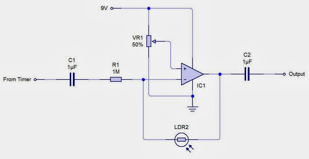
Before interfacing the circuit a decoupling capacitor should be added to stop any DC running through your output, unless you want to process the signal some more. A real thermin has pitch and volume control so you might want a light dependent attenuator as well.


The output of the timer is attached to a potential divider, the output responds positively to an increase in light. The op-amp is being used as a non-inverting buffer to reduce any loading effects on the potential divider due to its high input impedance. The capacitor decouples any DC so the output is solely AC allowing the direct connection with headphones. Remember to check the power rating of the output system you are using before you attach the circuit to prevent any damage.

Have fun!

Easy Pulse Width Modulation Circuit

Once you know how pulse width modulation is created then it is easy to create a circuit from that knowledge.

You will need three things:
  1. A sine wave source
  2. A triangle wave source (555 Timer)
  3. A differential amplifier (Op Amp)
I will explain this circuit in the context of continuous transmission e.g. a land-line phone.

If you examine the diagram below you will start to understand quickly how PWM works.


Picture: http://pcbheaven.com/wikipages/PWM_Modulation/

As the waves cross over the differential amplifier will saturate high or low. 
As the sine wave cuts through the top of the triangle wave the pulse generated is short because the peak of the triangle wave is very thin where as at the bottom of the triangle wave is wider and so the pulse generated will also be larger as a direct consequence. 
(I realise the picture is actually a sawtooth wave but there is no difference in the concept).

I'm sure you have grasped the concept by now, if not then the circuit diagram should be enlightening.


As you can see I have use the rising and falling of the RC in the 555 astable to create my triangle wave.
The frequency of the 555 can be changed by changing the RC connected to the chip.

I have also decoupled the triangle wave with a capacitor so it will swing around 0v just like the sine wave generator does. You will also want to do this to prevent any current escaping the RC pair but op amps have enough input impedance to do that for you.
The capacitor will also add capacitance to the RC so the total capacitance in the RC of the 555 will be 101uF, I have made the capacitance small enough so the effect on the timing element will be negligible.

As I said I will explain the circuit in terms of a continuous transmission signal.
You will find that the sine wave is represented by a signal generator, but the input sine wave could be anything as long as it's voltage is kept below the triangle wave voltage, otherwise it will not work properly.

Also if you have an increasingly complex waveform it will be better represented on the receiving end if you choose a higher frequency for the triangle wave, as it will give better resolution.

As a rule of thumb try to keep the frequency of the triangle wave at least ten times higher than the maximum sine wave frequency so the sine wave will be decently resolved when demodulated.

The depth of modulation is controlled by the ratio of input voltages, the depth of modulation will also affect the amplitude of the demodulated wave.