One of the most common integrated circuit chips you will come across is the "555 Timer", this is the chip I will be using in my sensor-controlled relaxation oscillator.

The circuit diagram for the 555 light controlled relaxation oscillator.
(The chip's pin numbers are displayed on the 555 symbol)
(R1 is necessary but the resistance doesn't really make any difference apart from changing the mark-space ratio of the output)
The frequency is inversely proportional to the RC constant: F = 1/RC
The RC constant is the product of the capacitance and the LDR's resistance. Remember that resistance/light proportionality changes with each LDR.
You may have your own preferences to what light level the oscillator responds to and it should not be hard to work out the values using the above formula.
I find the measurement of light to be a bit meaningless, so instead of checking the specifications (because I didn't have them :P) I vaguely measured the resistance of the LDR at my own light level definitions, my results were:
- Computer monitor = 1.2MΩ
- Shaded desk light = 380kΩ
- Non-L.E.D room lighting = 90kΩ
- Medium sunlight = 2kΩ
The highest resistance was used to determine the lowest frequency because frequency is inversely proportional to resistance. The lowest frequency the human ear can perceive is 20 Hz so I now have the variables I need to find the RC's capacitance. C = 1/FR
1/1.2MΩ x 20Hz = 41.67nF (A common capacitor value is 47nF hence I used one in my circuit)
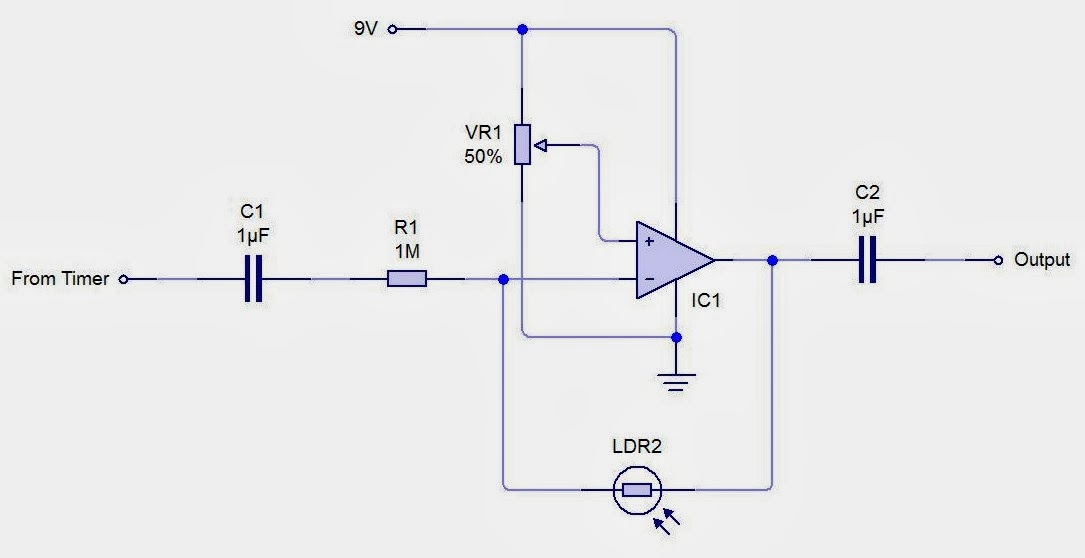
Before interfacing the circuit a decoupling capacitor should be added to stop any DC running through your output, unless you want to process the signal some more. A real thermin has pitch and volume control so you might want a light dependent attenuator as well.

The output of the timer is attached to a potential divider, the output responds positively to an increase in light. The op-amp is being used as a non-inverting buffer to reduce any loading effects on the potential divider due to its high input impedance. The capacitor decouples any DC so the output is solely AC allowing the direct connection with headphones. Remember to check the power rating of the output system you are using before you attach the circuit to prevent any damage.
Have fun!